System power modes and battery use
This application note outlines the different operating power modes of a LiNX system and its response to various battery voltages.
It details the three power modes a LiNX system can operate in at any one point in time, as well as what happens to a system and its modules as the system’s battery voltage reduces.
The following refers to LiNX systems with MR5.1 firmware and later. Systems with earlier firmware versions did not support some or any of the following concepts and parameters. A summary of differences between MR4.3 and MR5.1 firmware is highlighted in Table 4 — differences between LiNX MR4.3 and MR5.1.
System power modes
There are three power modes that a LiNX system can operate in:
-
Powered On,
-
Powered Off, or
-
Low Power.
However, the wheelchair user will only perceive two of these modes: Powered On or Powered Off. The third mode, Low Power, is an internal, intermediate state that allows the LiNX system to monitor itself for a predetermined time before powering off completely — if in Low Power mode, the system appears powered off to the user.

Figure 1: LiNX System power modes
Each power mode consumes different levels of current. These levels are described in more detail next.
Powered On
When in Powered On mode, the system and its modules are fully operational and are able to draw the most current from the battery.
Powered Off
When in Powered Off mode, the system and its modules draw an extremely small amount of current (that is, each module can draw somewhere in the order of 30-750 µA): power modules consume the most; other modules, such as the output module, consume far less. The amount of current drawn is different for each system, and is dependent on the particular LiNX system and the number and type of modules present.
One of the benefits of such low current consumption, when powered off, is that a fully charged system, comprising the maximum 16 modules, can still be in working order after being powered off and stored for six months.
Low Power
When in Low Power mode, as the name suggests, current is still consumed, but at a lower level than that of when in the Powered On mode. This allows the system to continue to monitor battery charging, allow for wake up from sleep (if enabled), and apply electronic braking to actuators from both the power and actuator modules.
Generally, modules that are performing a useful function remain powered on, while others power off completely. Modules that remain powered on use similar energy to when they are visibly powered on — the energy savings come from the modules whose display has been turned off.
Changing modes
The point at which the system moves from one power mode into another is dependent on system and user actions. Under normal operating conditions, the user powers the system on and off by pressing the power button. When powering on, the system enters the Powered On mode. When powering off, the system will appear to power off immediately, but in fact enters the Low Power mode. From the Low Power mode, the system can move back to the Power On mode or the Power Off mode depending on certain system and user actions. These are described in more detail next.
Figure 2 shows in more detail how and why the system moves from one mode into another.
From the Powered Off mode
If the system is currently in the Powered Off mode:
-
the system enters Powered On mode if the user presses the power button;
-
the system enters Low Power mode if a charger gets connected to the system.
From the Powered On mode
If the system is currently in the Powered On mode:
-
the system enters Low Power mode if the power button is pressed1
-
the system enters Low Power mode if the system goes to sleep2
-
the system enters Low Power mode when automatically powering down3
| NOTE |
|
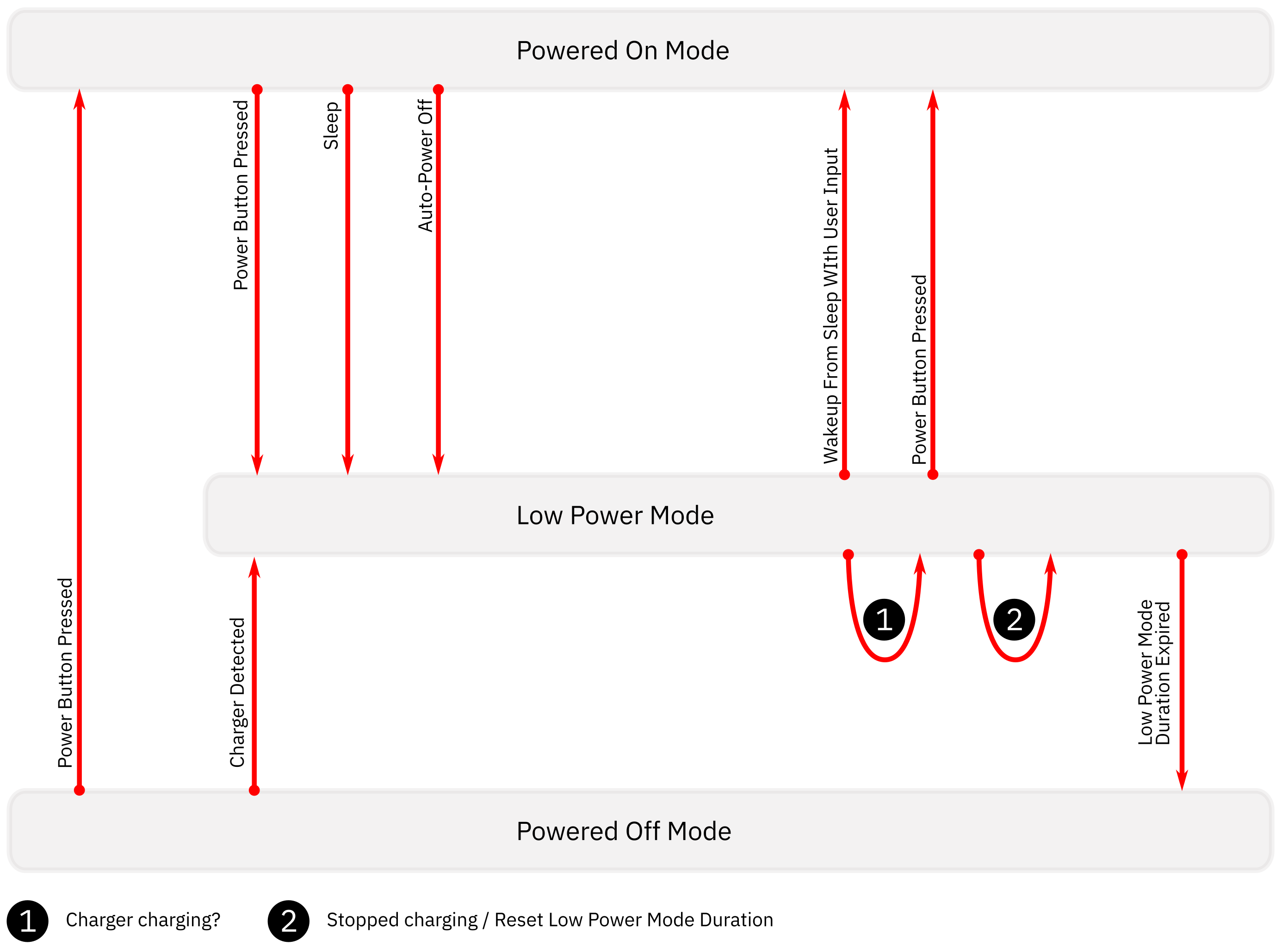
Figure 2: LiNX system power modes — detailed
From the Low Power mode
If the system is currently in the Low Power mode:
-
the system enters Powered On mode if the user wakes their system from sleep1
-
the system enters Powered On mode if the user presses the power button2
-
the system stays in Low Power mode if the battery is being charged3
-
the system stays in Low Power mode if the Low Power Mode Duration time has not expired4
-
the system enters Powered Off mode if the Low Power Mode Duration time has expired.
| NOTE |
|
The descriptions above are summarised in table 1.
Table 1 — Changing modes
|
Current mode |
Action |
Next mode |
|---|---|---|
|
Powered Off |
Power Button Pressed |
Powered On |
|
Powered Off |
Charger connected |
Low Power |
|
Powered On |
Power Button Pressed |
Low Power |
|
Powered On |
Sleep |
Low Power |
|
Powered On |
Auto Power Off |
Low Power |
|
Low Power |
Wake up from sleep with user input |
Powered On |
|
Low Power |
Power Button Pressed |
Powered On |
|
Low Power |
Charger Charging |
Low Power |
|
Low Power |
Stopped Charging / Reset Low Power |
Low Power |
|
Low Power |
Low Power Mode Duration Expired |
Powered Off |
Battery use
Low voltage behaviour
The LiNX system has been designed to cope with low battery voltages, and, in general, will not power itself down in response to voltage dips or sustained low voltage. However, certain operations are prohibited as the battery depletes. There are a number of benefits why the system is designed like this:
-
it prevents the system switching off while driving. This is particularly useful for systems with weak batteries, where the voltage can dip sharply to quite a low level.
-
it prevents the system switching off when the user, for example, drives into an obstacle, causing a current spike and a sharp voltage dip. The system remains on to provide what drive control it can.
-
it slows down the rate of discharge by disallowing the major sources of discharge (motors and actuators) from operating any further.
-
it allows the system to be diagnosed with the programming tools. If the system could not be powered on below a certain voltage, then it would be difficult to diagnose low batteries apart from measuring them with a voltmeter.
-
it allows the system to inform the user that it has a low battery.
Managing low voltage behaviour
Because the system has been designed to not turn off due to low voltage, if it is left powered on, the batteries will discharge further over the course of time. The rate of discharge depends on how many LiNX modules are in the system, as well as the number and type of third party devices connected. Fibre optic inputs, for example, are known to use a reasonably large amount of power as would a smart phone connected to the USB charger. The following describes how low voltage behaviour is managed; it is summarised in table 2.
Drive
Drive demand starts to be rolled back as the voltage falls. Typically, drive rollback starts at 21 V (set with Low Batt Rollback Start) and continues down to the Low Batt Rollback End setting (the default is
19 V but can be set as low as 17 V). The consequence of this drive rollback is a reduction in drive performance, but the intention is to preserve battery power so that the wheelchair has a chance to get the user back home.If the system is driving at the point it falls below 18 V, the wheelchair is allowed to continue driving but only until it gets down to 17 V, at which point it will stop.
Once driving stops, and if the voltage remains below 19 V (set with Low Batt Rollback End), driving cannot start again. Driving is prohibited below 17 V.
Actuators
Actuators are prohibited from operating when the battery is below
17 V.System
At around 13–10 V, the entire system powers itself off.
The above is summarised in table 2.
Table 2 — LiNX System low voltage behaviour
|
V limit |
Restriction |
Notes |
|---|---|---|
|
<=21–19 V |
Drive roll back |
Limp home mode |
|
<=19 V |
Drive prohibited |
If not driving |
|
<=17 V |
Drive prohibited |
|
|
<=17 V |
Actuators prohibited |
|
|
approx. 13–10 V |
System powers off |
|
Logging low voltage events
The following events and their meanings are logged during low voltage events. These events are logged and can be viewed using the programming tools.
-
FC2 Battery Too Low: the battery has dropped below 22.5 V (set with Batt Gauge Low Voltage Warning) — a 'low battery' warning based on the battery gauge voltage.
-
FC7 Battery Too Low: the battery dropped below 17 V. This is based on a less filtered value and so is triggered quicker in the case of fast changes in voltages.
-
FC2 Loss of Power: the battery instantaneously dropped below 16 V. This could be because the voltage dipped below this level, or that it has depleted lower than this voltage.
Managing battery life
There are a number of settings that can be used to help extend battery life, especially for systems that are not in use, or idle. These include:
-
enabling sleep timeout;
-
enabling auto power off;
-
setting low power mode duration to a shorter period.
Sleep timeout
Sleep timeout allows the system to enter Low Power mode after a set period of user inactivity. Sleep timeout is enabled with Enable Sleep Timeout and the user inactivity time is set with Sleep Timeout Duration.
The user can wake the system from Low Power mode by pressing the power button, or, if enabled (with Enable User Input Wakeup), by activating the user input (for example, deflecting the joystick).
However, if the user does not wake the system up within the time set by Low Power Mode Duration, then the system will enter Powered Off mode (see figure 2) if the batteries are not charging. When in Powered Off mode, the user input can no longer wake up the system; the power button must be used instead.
Automatic power off
For systems that may be left idle for long periods of time, the system will automatically power down after a 12 hour duration of user inactivity. This behaviour is enabled by default (see the parameter Automatic Power Off).
The automatic power off is an equivalent action to a user pressing the power button, so the system will enter Low Power mode before powering off completely.
Low power mode duration
As mentioned earlier, in Low Power mode, the system continues to monitor battery charging, allow for wake up from sleep (if enabled), and apply electronic braking to actuators from both the power and actuator modules.
Low Power mode uses less energy than Powered On mode, but significantly more than Powered Off mode. For this reason, the amount of time the system remains in Low Power mode should be limited.
If the system is not being charged, then the amount of time the system remains in Low Power mode is determined by the Low Power Mode Duration value. By default, this is set to one hour, but the time can be set to 3, 6 or 12 hours if required.
Measuring the state of charge
The battery voltage is measured by the power module, and is subsequently filtered by fast and slow filters.
The fast filtered battery voltage responds quickly (within seconds) for both charging and discharging, and is used:
-
to determine a Loss of Power event1;
to present warnings for high, low, and critically low voltage warnings1;
-
by the Traditional Battery Gauge.
The slow filtered battery voltage, which has a slower response (in the order of hours) is used by the Enhanced Battery Gauge.
The Enhanced Battery Gauge treats charging separately from discharging. It is important to note that the Enhanced Battery Gauge will not rise unless it has determined that the system is charging.
| NOTE | 1. These are not affected by the chosen battery gauge type. |
Comparing the traditional and enhanced battery gauges
Table 3 — traditional and enhanced battery gauge comparison
|
|
Traditional |
Enhanced |
|---|---|---|
|
State of charge at initialisation |
Averaged |
Averaged |
|
Charging detection |
Voltage and time based |
Voltage and time based |
|
State of Charge |
Based on filtered battery voltage |
Voltage-based algorithm using recent history to determine charging/ discharging state.
When discharging, the gauge will ignore recovery on the battery (that is, the gauge will not rise).
Progression of charging is monitored to promote better charging behaviour (the gauge will not jump to 100% as soon as a charger is connected). |
|
MyLiNX Data |
Recorded while powered on, charging, and in Low Power mode. |
Recorded while powered on, charging, and in Low Power mode. |
Differences between LiNX MR4.3 and MR5.1
There are a number of differences relating to the different power modes and behaviour based on battery voltage, as outlined above, between LiNX MR4.3 and MR5.1. These differences are highlighted in the table 4 next.
Table 4 — differences between LiNX MR4.3 and MR5.1
|
|
4.3 |
5.1 |
|---|---|---|
|
Wake from sleep (if enabled) |
Active for 6 hours once sleep commences. |
Active for the same time as Low Power Mode Duration. |
|
Automatic Power Off |
Not implemented in this version. |
Automatically power down the system after no user activity for 12 hours. Controlled by the distributor-level Automatic Power Off parameter. |
|
Low Power Mode Duration |
Not programmable — fixed at 24 hours. |
Programmable via Low Power Mode Duration parameter for 1, 3, 6, or 12 hours. In Low Power mode, the system continues to monitor battery charging, allow for wake up from sleep (if enabled), and apply electronic braking to actuators from both the power and actuator modules.
The remote module can now detect a charger being connected when the system is powered off and places the system into Low Power mode ready for monitoring the charging.
Low Power mode is now active for the programmed duration after the system is powered off and after charging finishes. It is also active during charging. |
|
Traditional Battery Gauge |
No information recorded during Low Power mode. MyLiNX 'Charging' status based on whether a charger was physically connected, rather than charging. |
MyLiNX battery statistics recorded during Low Power mode as per the Enhanced Battery Gauge. MyLiNX 'Charging' status now identical to Enhanced Battery Gauge whereby it is based on whether the power module believes it is being charged (voltage-based). This is also now recorded in Low Power mode. |
|
Enhanced Battery Gauge |
Re-estimation behaviour that tended to be overly conservative, and was triggered more often than intended by the design. |
Re-estimation behaviour now mirrors that of the Traditional Gauge. When the system is turned on, the battery gauge is adjusted to match the battery voltage (averaged during the start-up procedure). |