Conditional control IO
This application note describes conditional control IO and how to use it with a LiNX system.
Introduction
Before LiNX Market Release 6.1 (MR 6.1), configuring a LiNX system's control inputs and outputs (control IO) was limited to a simple rule-based model where a single output action was always activated in response to a single input action. We have termed this type of rule as an 'always' rule. For example, Figure 1 shows a rule that states when Switch 1 is pressed on the 10-way switch, control output 1 is always activated.
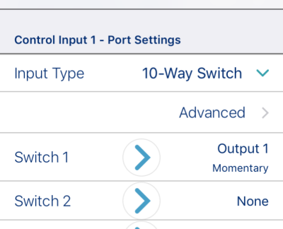
Figure 1: Control IO before MR6.1
With the introduction of conditional control IO, the ability to configure rules has been extended beyond the single always rule, allowing you to create:
-
multiple always rules — where one or more outputs are activated simultaneously from a single input. For example, when a button is pressed, tilt the user's seat and raise the leg rests;
-
conditional rules — where one or more outputs are activated from a single input if the specified conditions are valid. For example, when a button is pressed, toggle reverse if in a drive function; activate a single left click if in a mouse mover function;
-
conditional/else rules — where an output is activated from a single input if a specified condition is valid, otherwise (else) an alternative output is activated if the same, specified condition is not valid. For example, when the button is pressed, if the system is in the rest state, exit rest, else enter rest (Figure 2).
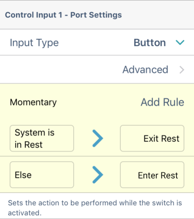
Figure 2: Example conditional control IO
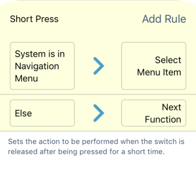
Figure 3: Conditional rule example
The benefit of conditional control IO is two-fold. Firstly, a single input can now be configured to activate multiple outputs. Secondly, a single input can be configured for multiple uses, each of which depends on specified conditions. This means that a single input can be used to activate one output if the system is in one state or function, and activate a different output when the system is in another state or function. For example, a button is used to select a menu item if 'the system is in the navigation menu', otherwise (else) it is used to select the 'next function' — Figure 3.
Conditional rules overview
The always rule
An always rule allows you to assign one or more outputs to an input with no conditions. To create an always rule, simply specify an input and assign one or more outputs to it. Since there are no conditions, an always rule can be summarised as:
|
When the INPUT is triggered, activate the OUTPUT. |
This states whenever the INPUT is triggered (for example, a button pressed), the OUTPUT assigned to the INPUT is always activated. It does not depend on any condition such as the state of the system or which function the user is currently operating in — if the input is triggered, the output is activated.
An always rule can have multiple outputs, which can be summarised as:
|
When the INPUT is triggered,
|
This states whenever the INPUT is triggered, activate all OUTPUTs assigned to the INPUT simultaneously.
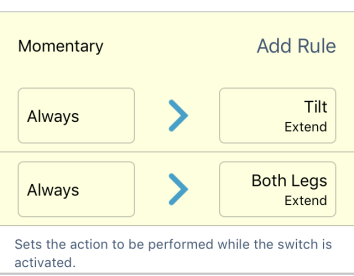
Figure 4: Always rule summary
For example, Figure 4 shows a multiple-output always rule for a button. Whenever the button is pressed, the seat will always tilt the seat (OUTPUT-1), and the leg rests will always raise (OUTPUT-2).
Conditional rules
A conditional rule allows you to activate an output from an input, subject to a condition. That is, whenever the input is triggered, only an output whose condition is true is activated. To create a conditional rule, you need to select an INPUT and specify one CONDITION and one OUTPUT. The conditional rule can be summarised as:
| When the INPUT is triggered, if the CONDITION is true, activate the OUTPUT. |
This rule states whenever the INPUT is triggered, activate the OUTPUT only if the CONDITION is true. Needless to say, if the CONDITION is false, the OUTPUT is not activated.
An input can be assigned multiple conditional rules, which can be written as:
|
When the INPUT is triggered,
|
This rule states whenever the INPUT is triggered:
-
activate OUTPUT-1 if CONDITION-1 is true
-
activate OUTPUT-2 if CONDITION-2 is true,
-
and so on, up to the number (n) of conditional rules defined.
If any of the conditions are false, the respective output is not activated.
| NOTE | When assigned multiple rules, each condition is evaluated individually and so it's possible that multiple outputs are activated at the same time if more than one of those conditions is true. This may or may not be your intention. |
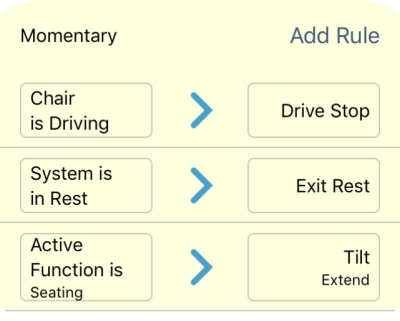
Figure 5: Conditional rule summary
For example, Figure 5 shows three conditional rules assigned to the momentary input of the button connected to Control Input 1. When the button is pressed:
-
if the wheelchair is driving (CONDITION-1), the wheelchair will stop driving (OUTPUT-1)
-
if the system is in the rest state (CONDITION-2), the system will exit rest (OUTPUT-2)
-
if in a seating function (CONDITION-3), the wheelchair will activate tilt (OUTPUT-3)
The conditional/else rule
A conditional/else rule allows you to activate an output from a single input if a specified condition is true. If the condition is not true, an alternative output is activated. To create a conditional/else rule, you need to select an INPUT, a CONDITION, and two outputs (OUTPUT-1 and OUTPUT-2). The first output you specify will activate if the CONDITION is true. The second output will activate if the CONDITION is false. The conditional/else rule can be summarised as:
| When the INPUT is triggered, if the CONDITION is true, activate OUTPUT-1, else activate OUTPUT-2. |
Figure 6: Conditional/else summary
For example, Figure 6 shows a conditional/else rule where if the system is in rest (CONDITION) when the button is pressed (INPUT), then the system will exit rest (OUTPUT-1). Otherwise (else), if the system is not in rest when the button is pressed, the system will enter rest (OUTPUT-2).
Creating rules
All rules are defined from a control input's control IO slot, such as the Momentary control IO slot, when the input type is set to button (Figure 7, left), or the Switch 1 control IO slot, when the input type is set to 10-way switch (Figure 7, right).
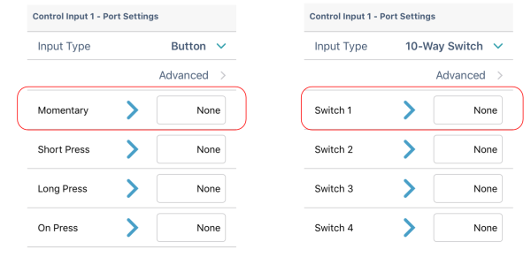
Figure 7: Control IO slot examples
To access these slots, you will need to set up a control input, using one of the LiNX Access tools (PC or iOS).
To set up a control input:
-
From the Home screen, scroll down and tap on Modules.
-
From the Modules screen, select the module that your input is connected to.
-
Locate the Port Settings for the control input that you want to configure.
-
Under Port Settings, tap on Input Type to reveal which input types are available for the input.
-
Tap on one of the Input Types to reveal its control IO slots: for example, Momentary, Band 1, or Switch
To create any rule for an input, you will need to either assign a condition and an output (see next section) or just assign an output (see section Assigning an output only).
Assigning a condition and output
Conditions are selected from the conditions list. To assign a condition to your rule, tap on the left-hand side of the control IO slot Figure 8 ①) to reveal the Add Rule button. Tap on Add Rule (Figure 8 ②) and the condition list is displayed. Select a condition from this list (Figure 8 ③) — the condition button will display your choice.
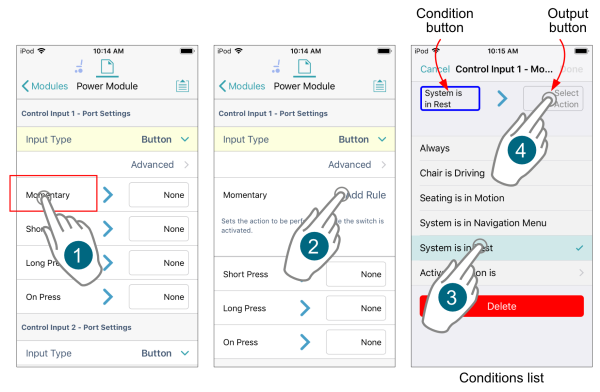
Figure 8: Assigning a condition and output — steps 1–4
Outputs are selected from the outputs list. To assign an output to this conditional rule, tap on the output button (Figure 8 ④ ) to display the output list. From the list, select an output, drilling down through the options as they are presented (Figure 9 ⑤ to ⑦). When complete, tap on Done (Figure 9 ⑧). A summary of the rule is displayed in the control IO slot.
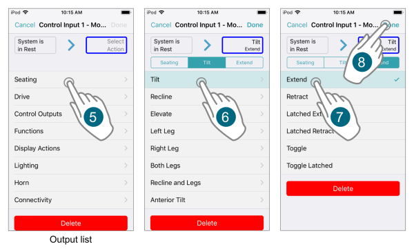
Figure 9: Assigning a condition and output — steps 5–8
Assigning an output only
Outputs are selected from the output list. If no rules have yet been defined, you can open the output list immediately by tapping on the right-hand side of the control IO slot (Figure 10 ①).

Figure 10: Assigning an output only
From the output list, select an output, drilling down through the options as they are presented (Figure 10 ② to ④). When complete, tap on Done (Figure 10 ⑤). A summary of the rule is displayed in the control IO slot.
If a rule already exists, and you want to add further outputs, tap on the left-hand side of the control IO slot (Figure 11 ①) to expand the slot and reveal the Add Rule button. Tap on Add Rule (Figure 11 ②), which opens the conditions list, and then tap on the output button (Figure 11 ③) to display the output list (Figure 11 ④). Continue to add an output as described above.
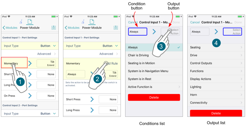
Figure 11: Assigning an additional output
You can easily switch between viewing the conditions list and the output list by tapping on the condition and output buttons, respectively.
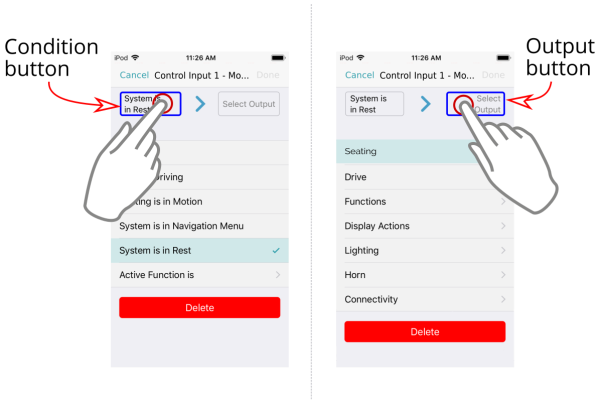
Figure 12: Toggling between conditions list and output list
Worked examples
The following examples show how to create the various rules discussed above.
Example 1 — Adding multiple always rules
In this example, we will add a multiple always rule that tilts the seat and raises the leg rests simultaneously. The input is a single momentary action from a button that is connected to CI-1 pin on the power module. The rules we want are:
-
rule output 1: tilt seat
-
rule output 2: raise both leg rests
From the LiNX Access tool, go to Modules | Power Module | Control Input 1 - Port Settings and then:
-
Select input type
-
Tap on Input Type and select Button (Figure 13 ①)
-
-
Select output 1
-
Tap on the right-hand side of the Momentary input item (Figure 13 ②) — a list of output actions is displayed
-
Tap on Seating (Figure 13 ③)
-
Tap on Tilt (Figure 13 ④)
-
Tap on Extend (Figure 13 ⑤)
-
Tap on Done (Figure 13 ⑥)
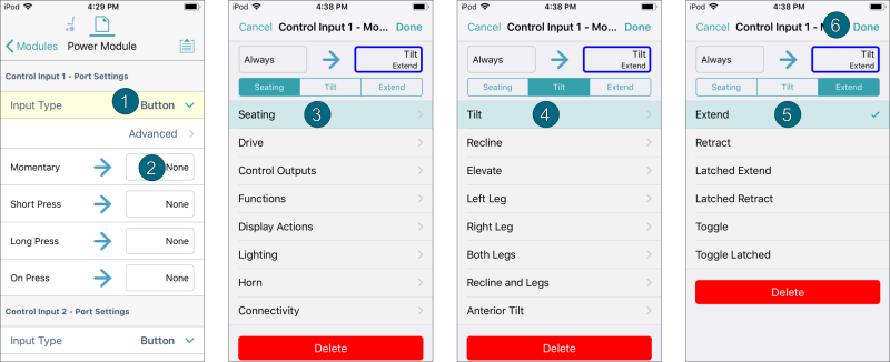
Figure 13: Select output 1
-
-
Select output 2
-
Tap on the left-hand-side of the Momentary input item (Figure 14 ①) — this will reveal the Add Rule button
-
Tap on Add Rule — a list of conditions is displayed (Figure 14 ②)
-
Tap on the output button — a list of output actions is displayed (Figure 14 ③)
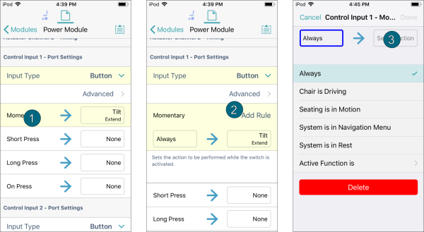
Figure 14: Select output 2 — part 1 -
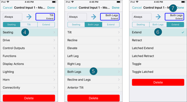
Tap on Seating (Figure 15 ④)
-
Tap on Both Legs (Figure 15 ⑤)
-
Tap on Extend (Figure 15 ⑥)
-
Tap on Done (Figure 15 ⑦)
-
Figure 15: Select output 2 — part 2
Example 2 — Adding a conditional rule
In this example, we'll add two conditional rules to determine the output from a single momentary action on a button, connected to CI-1 pin on the power module. The rules we want are:
-
rule output 1: if in a drive function, toggle reverse
-
rule output 2: if in Mouse Mover function, activate a single left click
From the LiNX Access tool, go to Modules | Power Module | Control Input 1 - Port Settings and then:
-
Select input type
-
Tap on Input Type and select Button (Figure 16 ①)
-
-
Select output 1
-
Tap on the left-hand side of the Momentary input item (Figure 16 ②)
-
Tap on Add Rule (Figure 16 ③) — a list of conditions is displayed
-
Tap on Active Function is (Figure 16 ④)
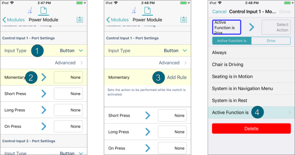
Figure 16: Adding a conditional rule - output 1 — steps 1–4
-
Tap on Drive (Figure 17 ⑤)
-
Tap on the output button (Figure 17 ⑥) — a list of actions is displayed
-
Tap on Drive (Figure 17 ⑦)
-
Tap on Toggle Reverse (Figure 17 ⑧)
-
Tap on Done (Figure 17 ⑨)
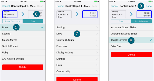
Figure 17: Adding a conditional rule - output 1 — steps 5–8
-
-
Select output 2
-
Tap on Add Rule (Figure 18 ①) — a list of conditions is displayed
-
Tap on Active Function is (Figure 18 ②)
-
Tap on Mouse Mover (Figure 18)
-
Tap on the output button (Figure 18 ④) — a list of actions is displayed
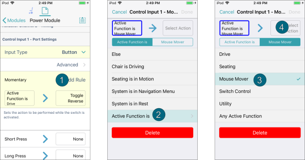
Figure 18: Adding a conditional rule - output 2 — steps 1–4
-
Tap on Connectivity (Figure 19 ⑤)
-
Tap on Mouse Left Click (Figure 19 ⑥)
-
Tap on Single (Figure 19 ⑦)
-
Tap on Done (Figure 19 ⑧) — the rule summary is displayed (Figure 19 ⑨)
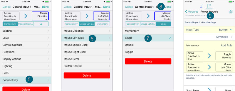
Figure 19: Adding a conditional rule - output 2 — steps 5–9
-
Example 3 — Adding a conditional/else rule
In this example, we'll add a conditional/else rule for a button press that will allow you to toggle in and out of the rest state. That is, exit rest if the system is in rest, otherwise (else) enter rest when not in rest. The outputs are:
-
rule output 1: Exit rest (if in the rest state)
-
rule output 2: Enter rest (else)
The button is connected to the CI-1 pin of the power module. From the LiNX Access tool, go to Modules | Power Module | Control Input 1 - Port Settings, and then:
-
Select input type
-
Tap on Input Type and select Button (Figure 20 ①)
-
-
Select output 1
-
Tap on the left-hand side of the Momentary input item (Figure 20 ②)
-
Tap on Add Rule (Figure 20 ③) — a list of conditions is displayed
-
Tap on System is in Rest (Figure 20 ④)
-
Tap on the output button (Figure 20 ⑤) — a list of display actions is displayed

Figure 20: Adding a conditional/else rule - output 1 — steps 1–5
-
Tap on Display Actions (Figure 21 ⑥)
-
Tap on Exit Rest (Figure 21 ⑦)
-
Tap on Done (Figure 21 ⑧)
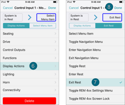
Figure 21: Adding a conditional/else rule - output 1 — steps 6–8
-
-
Select output 2
-
Tap on Add Rule (Figure 22 ①)
-
Tap on the output button (Figure 22 ②)
-
Tap on Display Actions (Figure 22 ③)
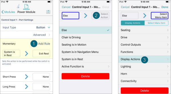
Figure 22: Adding a conditional/else rule - output 2 — steps 1–3
-
Tap on Enter Rest (Figure 23 ④)
-
Tap on Done (Figure 23 ⑤) — the rule summary is displayed (Figure 23 ⑥)
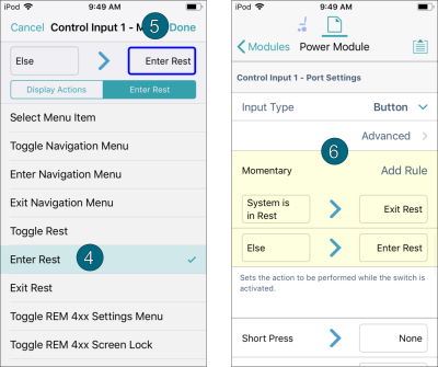
Figure 23: Adding a conditional/else rule - output 2 — steps 4–6
-